Homemade Digital Picture Frame
 I came across a website years ago and then upon researching found many documenting the process of turning an old laptop into a picture frame.
The problem was I needed a laptop.
I had obtained a few over the years, but they only supported 256 colors on the screen, which ruins picture quality in a hurry.
Then my sister inlaw obtained one that was ultimately saved from the trash somewhere.
Since it was behind in tech and the hard drive was having problems, it was given to me after making her aware of my situation.
So, now I have another project I can scratch off my list.
I came across a website years ago and then upon researching found many documenting the process of turning an old laptop into a picture frame.
The problem was I needed a laptop.
I had obtained a few over the years, but they only supported 256 colors on the screen, which ruins picture quality in a hurry.
Then my sister inlaw obtained one that was ultimately saved from the trash somewhere.
Since it was behind in tech and the hard drive was having problems, it was given to me after making her aware of my situation.
So, now I have another project I can scratch off my list.
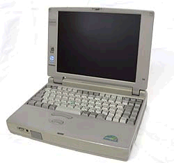
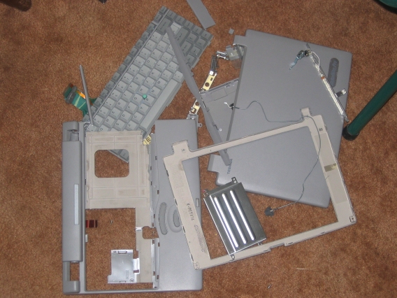
This first image are the pieces of the Toshiba Satellite Pro 430CDT I did not need. Basically I kept the bottom of the unit since everything was screwed into it and stripped every other none electronic part. Regrettably this laptop is thicker than most, even for its time, but I was able to hide it pretty well.
Next image shows the unit coming together. I hand made the frame out of oak trim and also used oak on the boxing around the guts. A glass and black matte were obtained through Hobby Lobby and put into the boxing first. The screen was then centered as best as possible (it was very difficult to do) and duck taped to the matte.
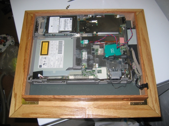
This image shows the guts now put into the boxing over the screen. Despite the hard drive going bad (bad sectors and such) I decided to use it. You can see it in the upper left side. After booting to DOS I create a RAM Drive in memory and shut down the hard drive. Because I am running my program in memory, the picture frame is 100% silent running. Note the hole in the bottom of the unit. This is so I can still plug in a keyboard for future program modification.
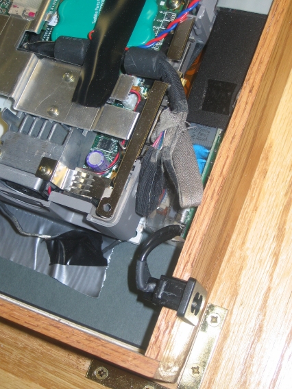
Here's an image close up of the power unit. Unlike most laptops, this one had it's transformer internal. It was put in along side the guts and a notch in the boxing allowed the AC connector. You can see the ribbons running by the power supply to the screen here.
Next image shows the linkage I made for the on/off button. A small wooden dowel extends to the outside and when pushed pushes the original button on the unit.
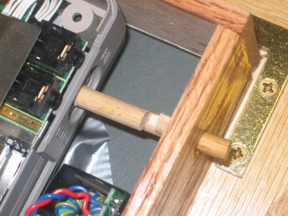
Here's an image showing a nut and bolt that basically latches the labtop base to the framing. It left the guts very secure and kept them from moving around. I used additional hardware to secure the back of the frame which makes it removeable if need be in the future.
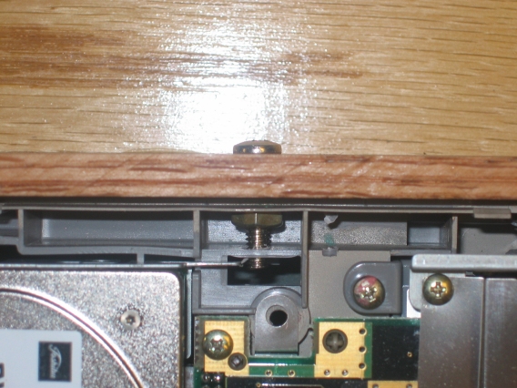
This image shows the back of the project. Note the cut out for the CPU heat sink. Originally I was going to have it covered, but it got pretty hot and my back actually fit better once it was left open. Several air holes were drilled along the top to encourage air flow through the system. Additional smaller air holes were placed over the video card and power supply. Air should flow out through these holes and in from the keyboard hole and heat sink cut out.
Next image shows the AC adaptor and if you look close you can see the wooden on/off button. The frame is held up with an oak panel support held by a brass hinge. Because the panel is so thin, the hinge was glued on. A small amount of ribbon keeps it from over extending.
This image shows the side with the CD cutout. When the unit boots, it copies all the images on the CD to the drive in memory. So, the CD drive does not run after the initial copying. At the moment I have 24 meg of the 32 meg of RAM assigned to the virtual drive. That's enough for around 100 images, resized to 800x600 (the native resolution of the screen)
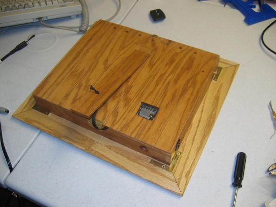
 Finally, the close up image of the end result.
It works great.
I used a DOS program called LxPic to cycle through the images.
It was copied to the drive in memory and ran from there with a call from the autoexec.bat.
I changed a setting to use low power on the screen (via the BIOS).
The higher setting tended to wash out the images and turning it down will probably extend the life of the screen.
Pictures are hard to see in a bright room or in direct sun as one can imagine, but that is to be expected.
The images are easily viewed from any horizontal angle despite being a laptop screen.
Viewing more than 45 degrees in the vertical though and the image fades or looks funny.
Given that it is displayed near eye level or pointed at the viewer, none of this really effects the image.
Finally, the close up image of the end result.
It works great.
I used a DOS program called LxPic to cycle through the images.
It was copied to the drive in memory and ran from there with a call from the autoexec.bat.
I changed a setting to use low power on the screen (via the BIOS).
The higher setting tended to wash out the images and turning it down will probably extend the life of the screen.
Pictures are hard to see in a bright room or in direct sun as one can imagine, but that is to be expected.
The images are easily viewed from any horizontal angle despite being a laptop screen.
Viewing more than 45 degrees in the vertical though and the image fades or looks funny.
Given that it is displayed near eye level or pointed at the viewer, none of this really effects the image.